 See a video of the piece working on Youtube
View the code for programming the Arduino Uno on GitHub
The origins of the project:
This past June (2015), I had the pleasure of visiting the MIT (Massachusetts Institute of Technology) campus for a week to work with Jana Dambrogio in the Wunsch conservation lab along with our fellow colleague Brian Beidler. During that wonderful week, I met Jie Qi, a PhD student in the MIT media lab. Jie and I had a chance to show one another what we had been working on and discovered many common interests. So when I received an email from her this September, with an invitation to participate in her thesis project, I jumped at the chance. My contribution would be to create something from a supply of Jie’s circuit stickers, Chibitronics, with the option of incorporating more components if needed. The goal was to create something with the given supplies, but the rest was open to our interpretation. It took less than one second to decide.
In our pack of goodies was a Chibitronics starter kit, an extra roll of copper tape, white and multicolored LED stickers, effects add ons, sensor add ons, gator clips, a USB power source, and a one foot square canvas on which our project would be built.
When I sat down to really think about what I would do for this, immediately bioluminescense came to mind. It is always on my mind, really. Who can resist the glimmer or flash of light emitted from a plant, animal, bug, or bacteria? It is something that borders on super powers. There is something that pulls us towards an unexpected light source drawing our curiosity in to find out more.
My interest in bioluminescence and how that could be represented by LED lights was clearly what I wanted to pursue. Of the many creatures that utilize this light emitting chemical reaction, I needed to chose one or two to focus on. The way I was able to do so was to ask why these organisms do it in the first place.
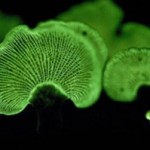
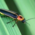
A fish, like the angler, will use light as a lure in the darkness of the ocean to attract its meal. Small shrimp emit a cloud of light so they can escape predators. I have a huge fascination with the ocean, but I couldn’t manifest a mental image of my project. So I went to land and finally came to fireflies (a common beetle) and foxfire (a fungus). The firefly flashes to attract a mate. Foxfire glows like a lantern in the middle of a dark forest to attract bugs that will crawl all over it and then walk away carrying its spores as they walk away. This idea of light as an invitation for an interaction fits perfectly with the way I think humans are attracted to lights ourselves.
So there was nothing left to do next but to start making some fungus, something I hope to be known for saying in the future.
Putting it together:
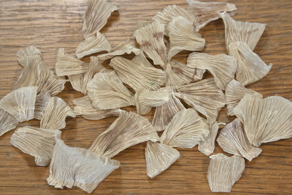 To create the foxfire mushrooms, I went to the handmade paper I have acquired from Andrea Peterson of Hook Pottery Paper. Needing the ability to mold the paper without the risk of tearing it in the process was very important, but because I wanted them to glow, the paper I used had to have some transparency as well. A few of the pieces were lightly painted with brown drawing fluid, before wetting, to simulate natural color variations. The paper was saturated with a spray bottle, then scrunched on the table to create the mushroom gills. The pieces were clipped at the base and were left to air dry. With a water pen, I was then able to apply water to the areas that I wanted to further sculpt.
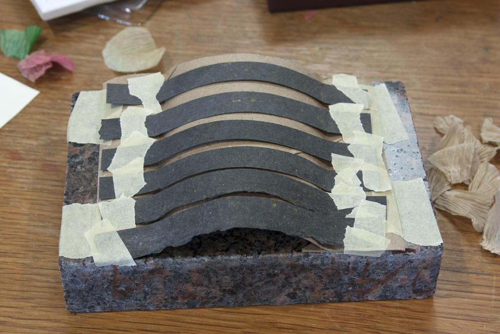 Next, was to figure out the arrangement of the foxfire as they would appear to grow on a log in nature. It was hard to think in the round, and I felt like it would be beneficial to have the foxfire built up on strips of paper rather than directly on the log. So I created a curved substructure from cardboard then used lots of masking tape to keep each strip in place.
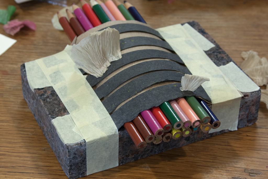 I didn’t worry about where the lights would go at this point. It would be easier to figure out their placement once the mushrooms were arranged on the log. As I added the mushrooms, I realized my cardboard wasn’t holding the shape enough to attach each piece, so I shoved colored pencils in there to fit the contour and they made a perfect stabilizing aid.
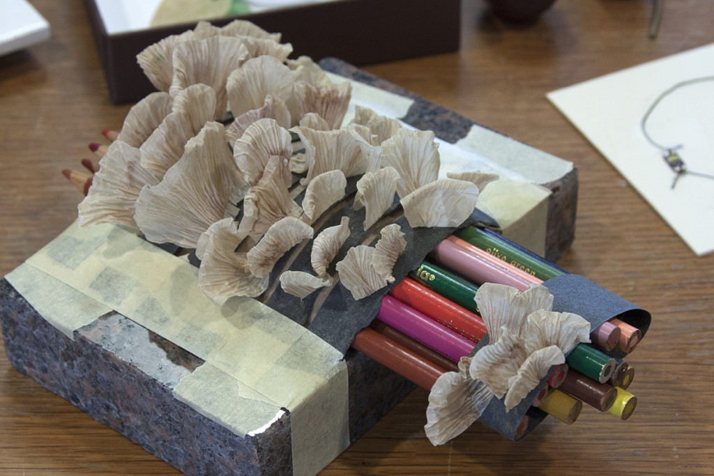 The pencils served a second purpose as I needed to arrange the separate clump of mushrooms that would be placed further down the log.
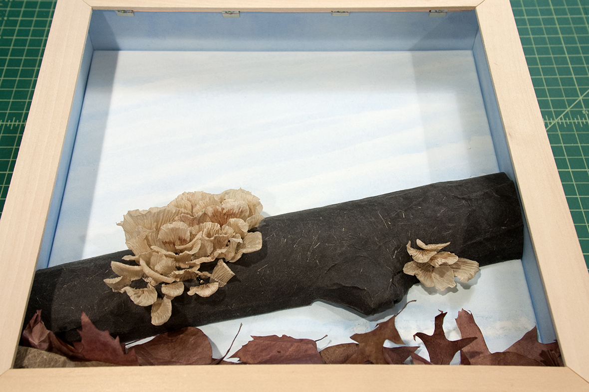
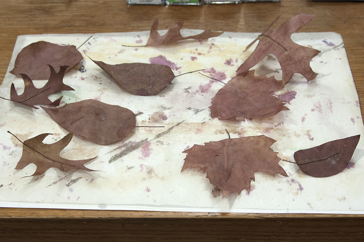 As I was making the foxfire, it occurred to me that the bottom of the piece would not only look bare, but the log would appear to float without something to give it context. Staying true to the facts of foxfire, it grows on logs, but specifically on those that are on the forest floor, because of the moisture. So leaves were made from more handmade paper by first cutting out their shapes, then applying a few thin layers of drawing fluid until I achieved the color I was looking for, and finally allowing them to air dry for maximum “dry leaf curl”. Stems were made with painted threads glued on.
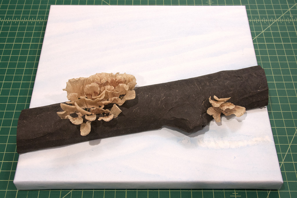
The log was then made with a heavy cotton and straw handmade paper that was sprayed with water, then wrapped around a log I had in the backyard. Once dry, it held its shape perfectly! The strips of paper that had the mushrooms on them were glued in place.
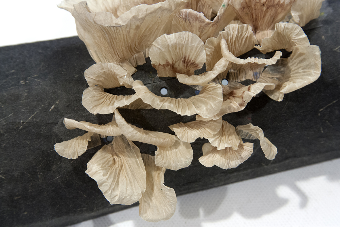 With that done, it was time to consider the LEDs and their placement. I was looking to achieve the effect of glowing mushrooms, so my initial thought was to put the lights behind the paper so they would be hidden, and let them illuminate from below. I punched holes where I thought they were needed, but after testing lights in a few spots, there was not enough light to do what I wanted. So I switched to a different type of LED that could be hidden among the mushrooms.
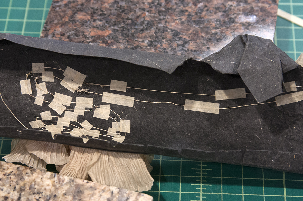
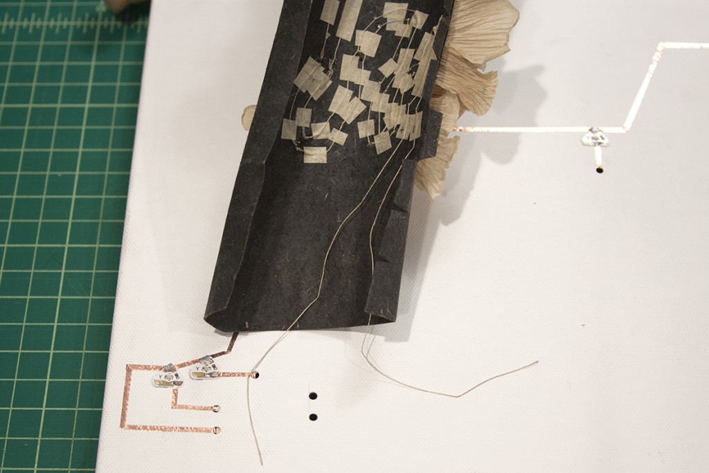
The type of light I used requires conductive thread or wire as opposed to the copper tape that I was given. I used thread to create the circuitry which was tied from light to light, each thread traveling on the “back” of the log, until they were all connected. The action that these lights were to perform was to fade on all at once, for a period of time, then fade off together. This meant that they could all be on the same parallel circuit. Because of the windy path the thread travels, there was the risk of the threads shifting and touching one another, which would cause a short circuit. Once the threads were where I needed them, I used pieces of glued paper to fix them in place (below).
 Next to consider was the circuitry for the rest of the piece. The fireflies would be the next major part, but I had also decided on another aspect of the narrative I was setting out. Having the foxfire glow and the fireflies flash didn’t give much information other than those things light up. The actions needed context. As I was forming the previous components, it occurred to me that what was needed was just an indication of time. These things only perform after dark. So the passage of time could be conveyed to the viewer by two more circuits of lights: daylight and sunset.
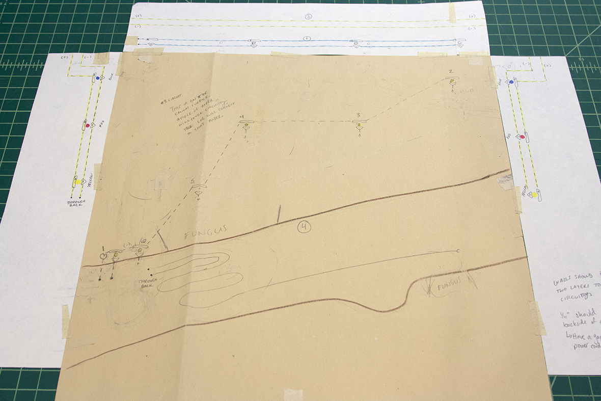 The above drawing is a plan for how I thought the lights and circuitry would be organized on the canvas and the frame I would have to build to hold them.
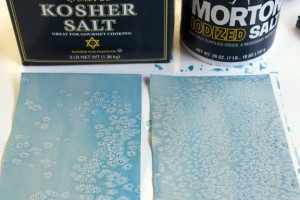
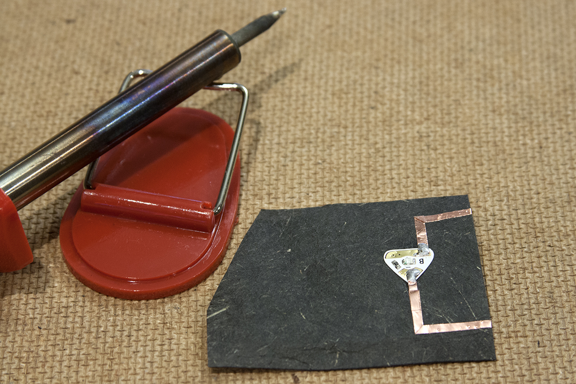 The remainder of the circuitry for this piece would be done with the Chibi sticker LEDs and copper tape. In order to ensure that the connections between the lights and the tape wouldn’t fail over time, it was suggested that they be soldered in place. I don’t have reason to solder often, so I wanted to do a test (above) to be sure I knew what I was doing. Plus, soldering is ridiculously fun.
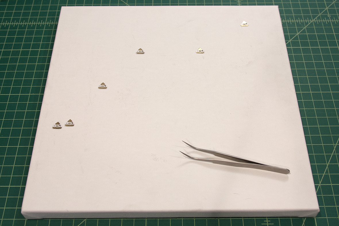 To begin, the firefly lights (yellow) were put in place. The fireflies would be made to look like they were communicating with one another, flashing back and forth, which would take six lights. Since each of these lights would produce its own action, they each had to be on their own circuit.
 The negative nodes of the lights could be connected to one another, but each of the positive charges had to travel to a separate pin on the microcontroller. (By this time, I figured out I needed a microcontroller because I had added several circuits that needed to be told what to do independently from one another.)
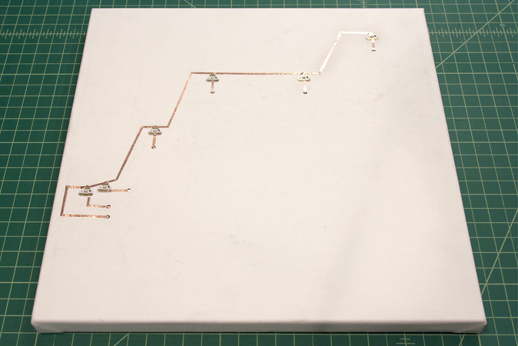
 To be efficient with my circuitry, each positive connection traveled to the back of the canvas through a hole. They could be connected with the rest of the circuits at a later point.
 The log was then used to figure out where its circuit would pierce the canvas but not attached yet.Â
The log was then used to figure out where its circuit would pierce the canvas but not attached yet. 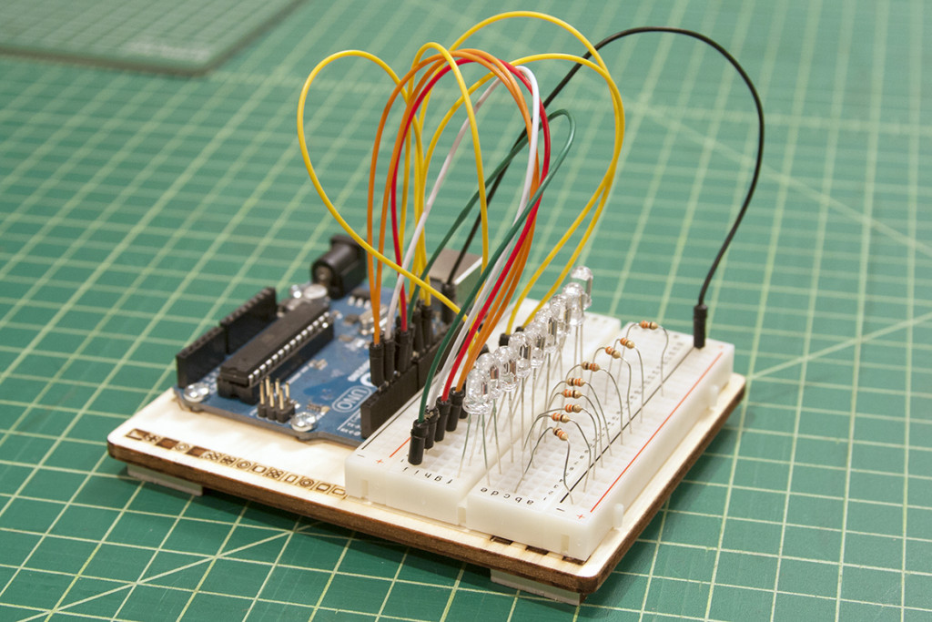 At this point, I wanted to be sure all of the things I had planned for the piece would function. As I was getting help with the coding aspect of the project, I needed to give time for that as well. The above photo includes an Arduino Uno microcontroller, mounted on the left, and a bread board, mounted on the right. I would use a microcontroller just like the one in the photo, but the breadboard just helps us create the circuits that would be used in the piece without having to have the actual piece ready. (See a video of the model doing one of the tests). The code was written and it could do everything I wanted!Â
At this point, I wanted to be sure all of the things I had planned for the piece would function. As I was getting help with the coding aspect of the project, I needed to give time for that as well. The above photo includes an Arduino Uno microcontroller, mounted on the left, and a bread board, mounted on the right. I would use a microcontroller just like the one in the photo, but the breadboard just helps us create the circuits that would be used in the piece without having to have the actual piece ready. (See a video of the model doing one of the tests). The code was written and it could do everything I wanted! 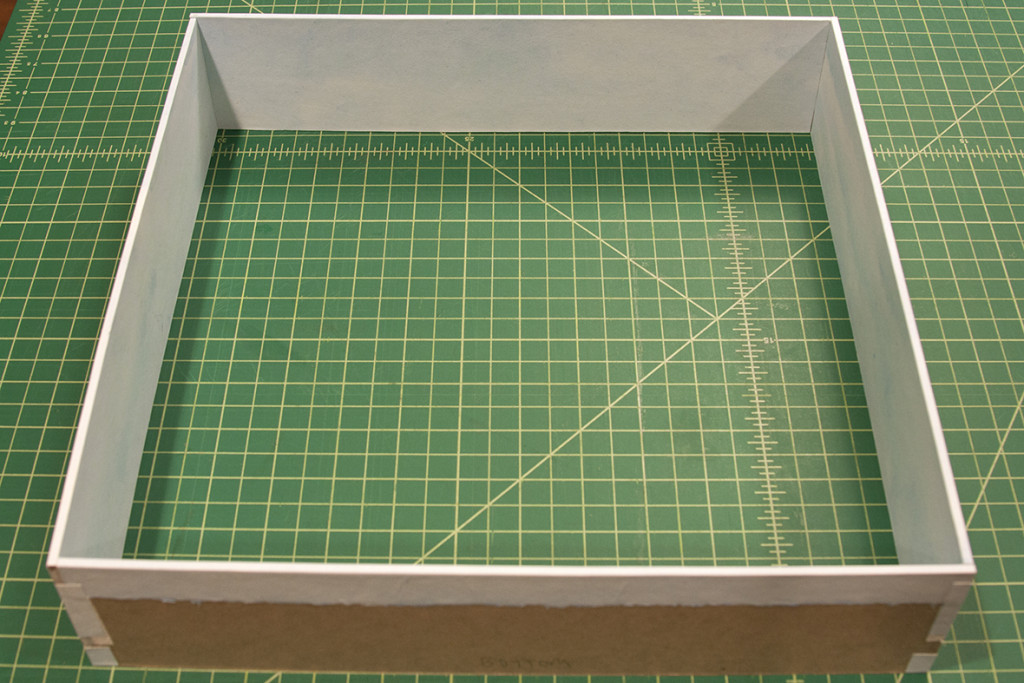 I mentioned the need of a frame for the daylight and sunset lights. This frame was made from binder’s board covered in white handmade paper that I had painted to simulate light blue skies. Another piece of paper was painted the same way to cover the canvas.
 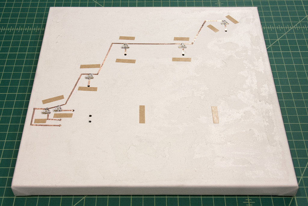 The above photo shows double sided tape around the circuitry so that the paper would sit directly on top of the lights. I tried gluing the paper in place first, but it warped in a way that was much too distracting.Â
The above photo shows double sided tape around the circuitry so that the paper would sit directly on top of the lights. I tried gluing the paper in place first, but it warped in a way that was much too distracting. 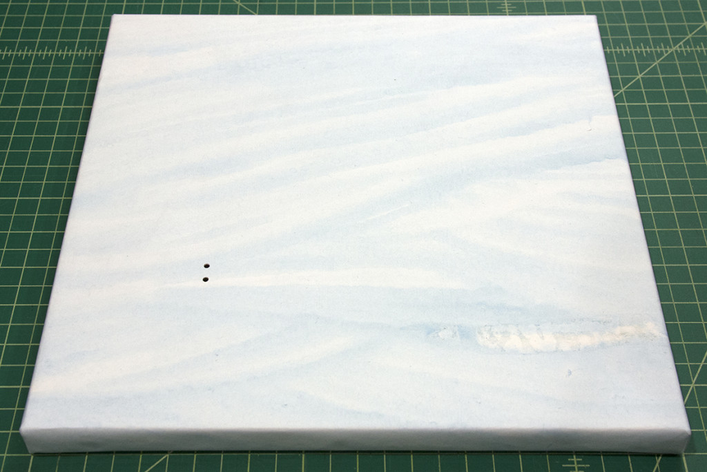 The background paper was secured to the tape, and the edges were wrapped and glued to the back of the canvas. In bookbinding, this is referred to as “drumming”.
 The log was then attached and the conductive threads were fed through to the back.
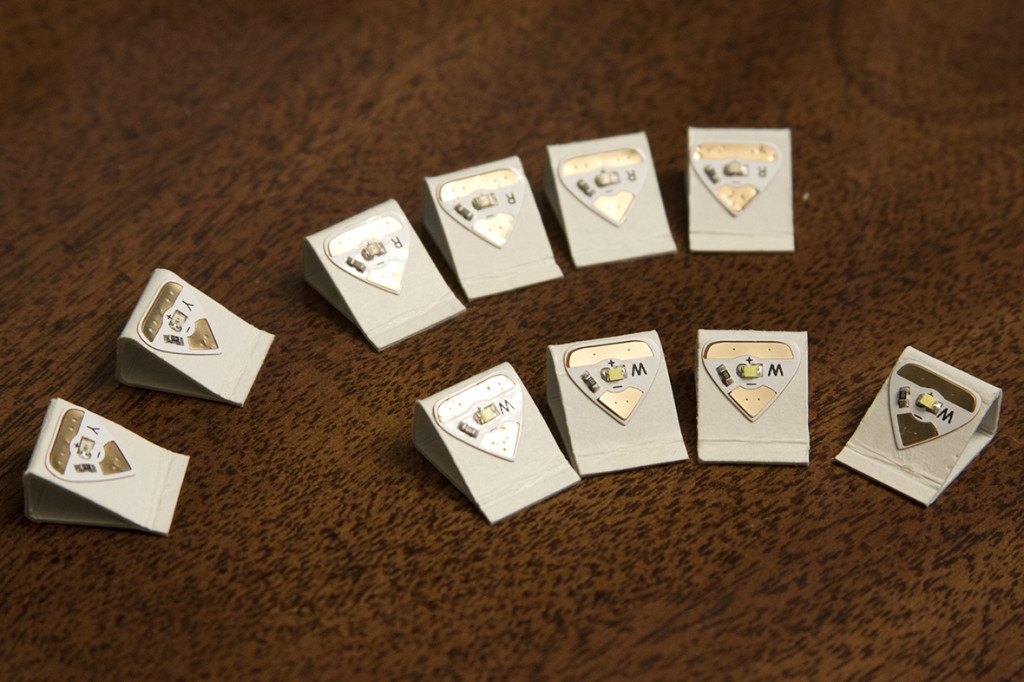 The lights that would create the effect of daylight giving way to sunset would be mounted to the board frame. In order to cast their light effectively on the piece instead of just across it, I mounted them to small wedges I made from thick folder stock.
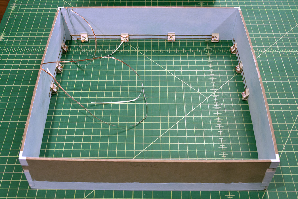 This is a view of the frame with the lights in place along with their copper tape circuits. the circuits would travel to the outside of the frame to connect to the rest of the circuits on the back of the canvas. All connections were soldered once fixed.
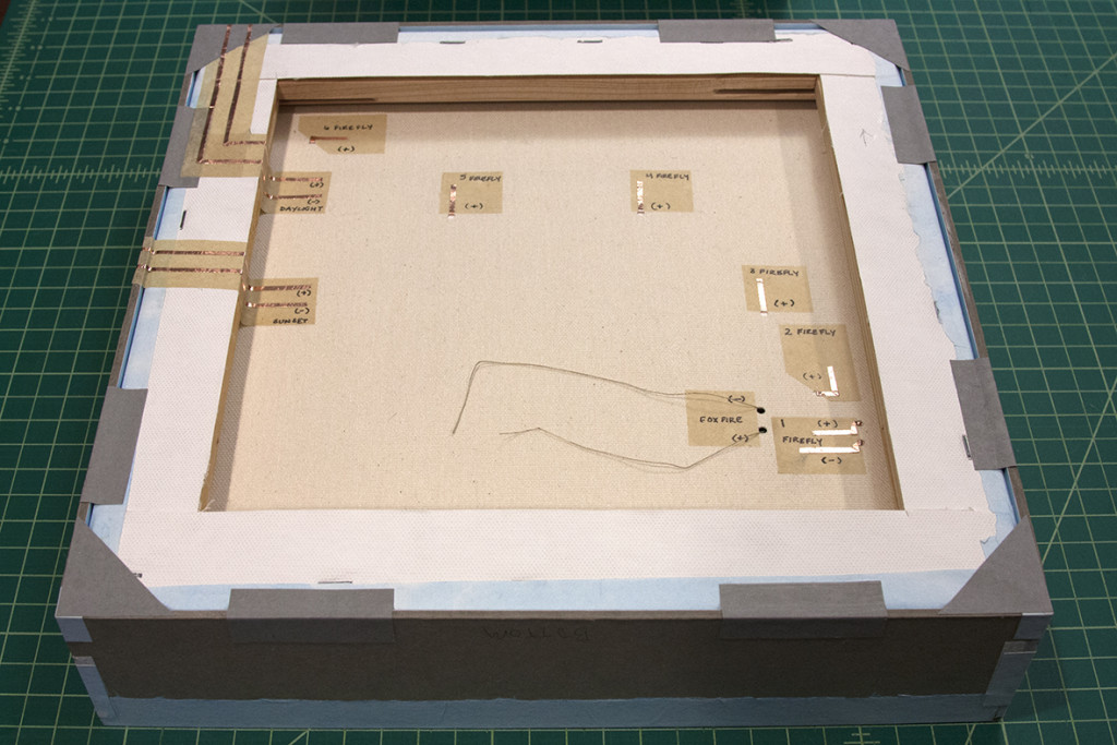 The above photo shows the frame connected to the canvas and the circuits wrapped in place. The below photo is a detailed shot. The yellow paper that is under the copper tape was glued there first provide a smooth surface for the copper tape to stick to reliably.
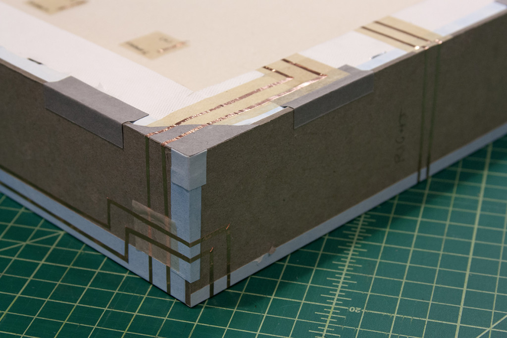 With all the circuits now in place on the back of the canvas, I just had to figure out how to connect them all to the microcontroller. The circuits were made with two different types of conductive materials, neither of which could make a connection to the Arduino Uno. So I would have to use wire to connect everything to the brain.
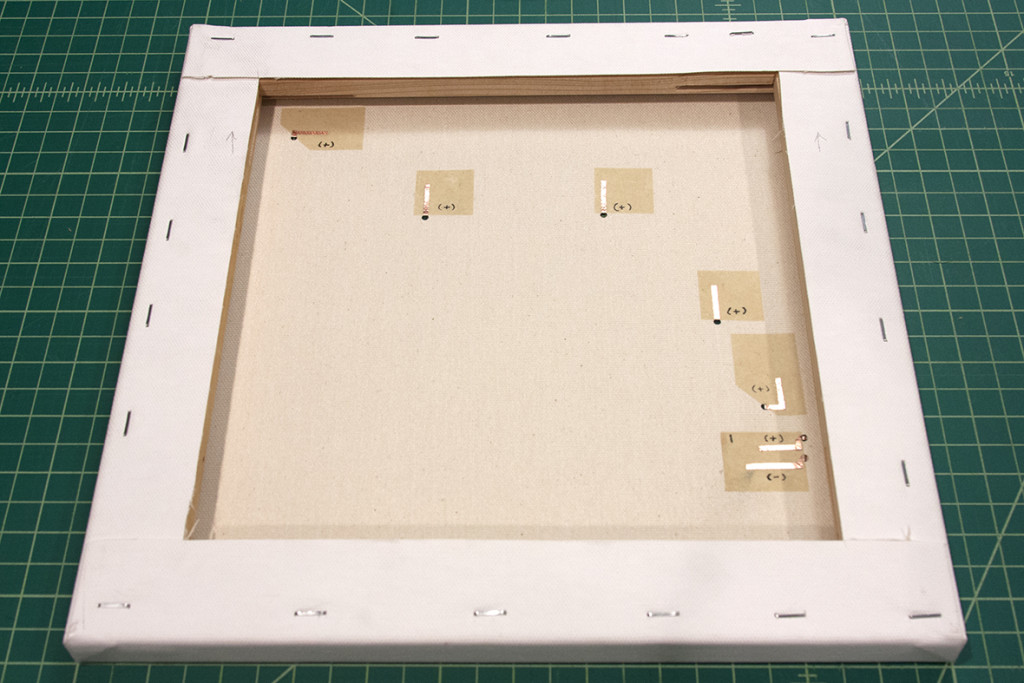
 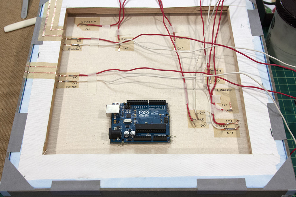 Wires were soldered to each line. Then, the wires were shaped, as neatly as possible, to get to the Arduino. At this point, the Arduino was not connected to the canvas because I wanted room to work on securing the wires.
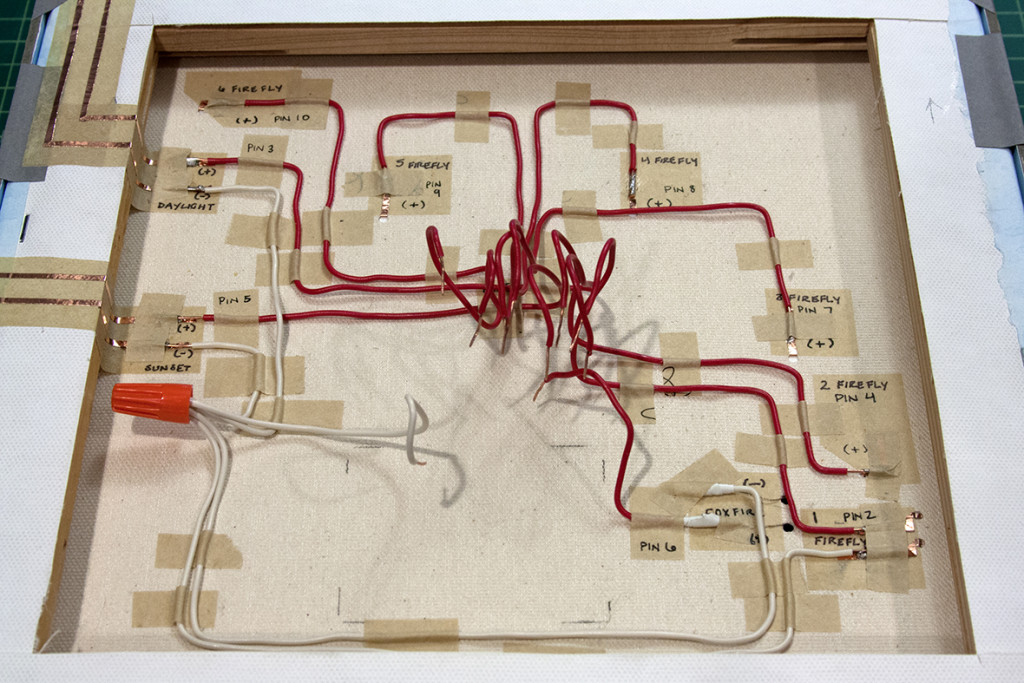 I glued down the wires with paper and labelled each one’s pin location as it would correspond with the microcontroller. The Arduino was glued in place and the wires connected.
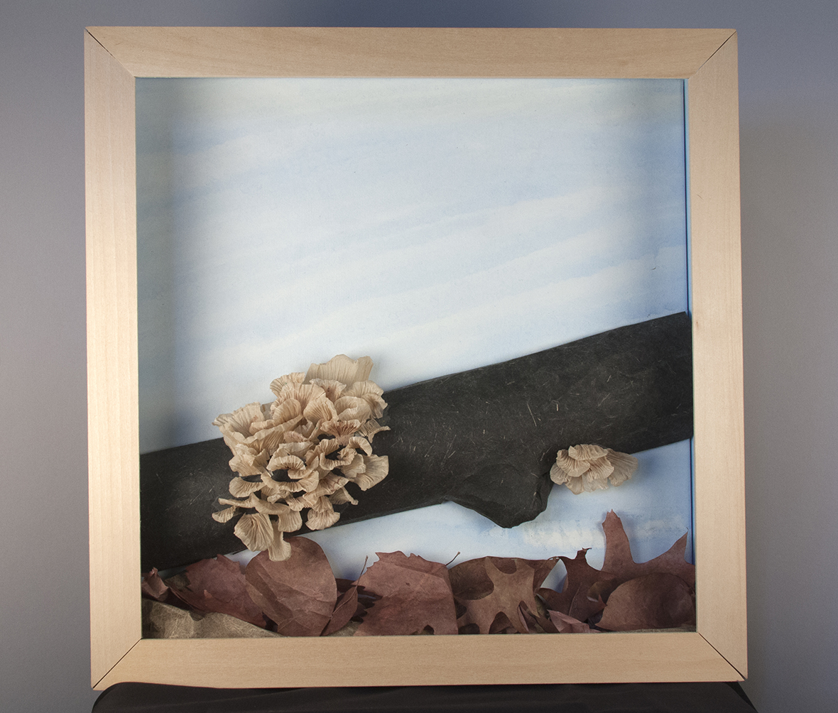
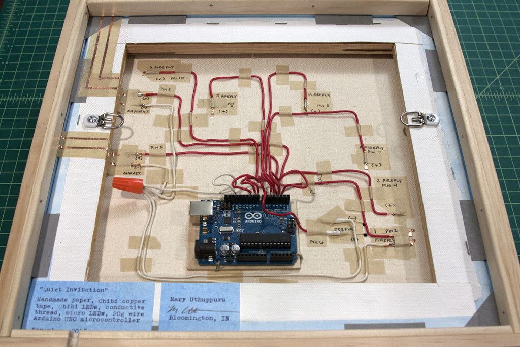 Everything was tested a final time. A wooden frame was built around the piece to hide and protect the exterior circuits which would also help hide the lights on the front of the piece.
See a video of the piece working on Youtube
View the code for programming the Arduino Uno on GitHub