CIRCUITRY
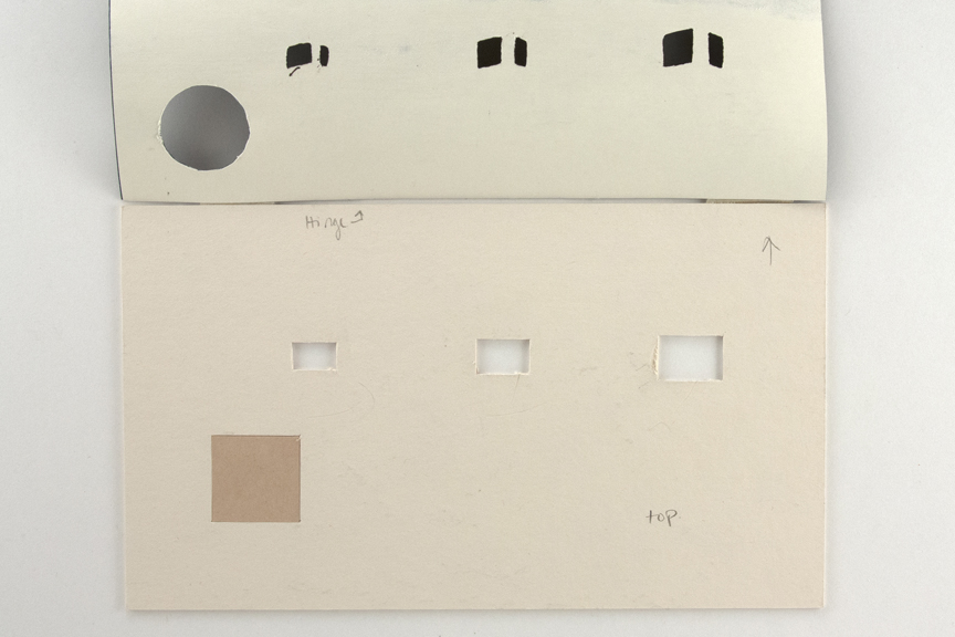
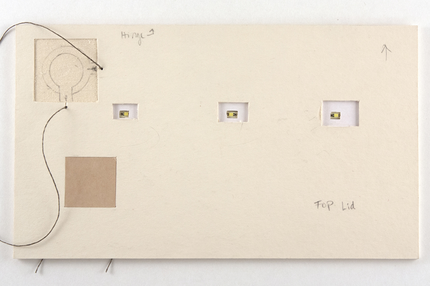
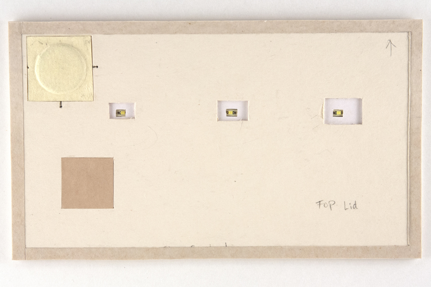
Using the decorative lid paper, transfer the holes from the lanterns onto the TOP LID board and cut a rectangle from the board just larger than the lantern openings. (Temporarily tape into place if necessary)
 img. 12
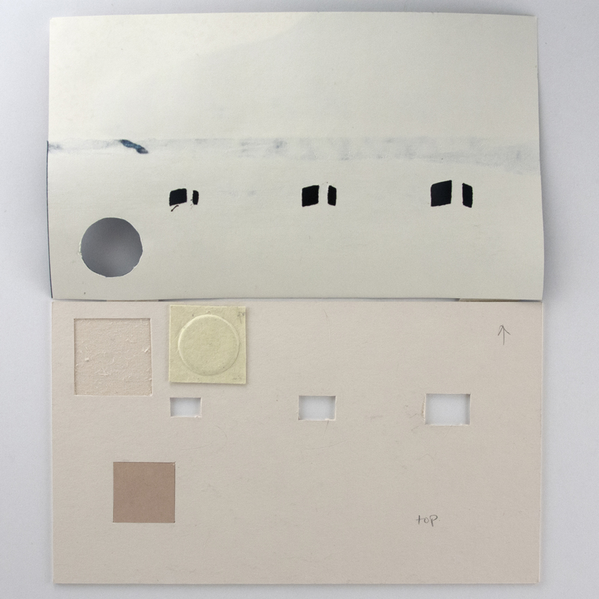
Again, using the design, put the button in place so that you can transfer its contour. Cut around the button base and peel away enough material to set the base flush with the board surface.
 img. 13
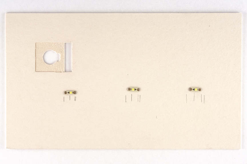
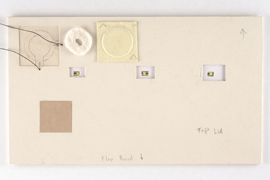
Using the design and the TOP LID board, determine where you want the LEDs to be positioned on the BOTTOM LID board.
 img. 14
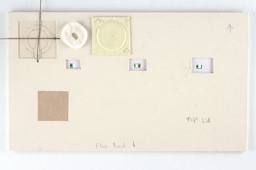
Trace around the lights and make sure they are in the right place by putting the boards face to face.
Keep in mind, the light is positioned slightly off center on the individual boards. Also, you will need your lights to be positioned so the (+) and (-) are on the correct sides (refer to your drawing)
Cut down deep enough so that the board of the light sits flush. (Place the light in the opening face up and feeling for a difference in thickness)
 img. 15
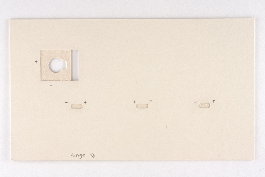
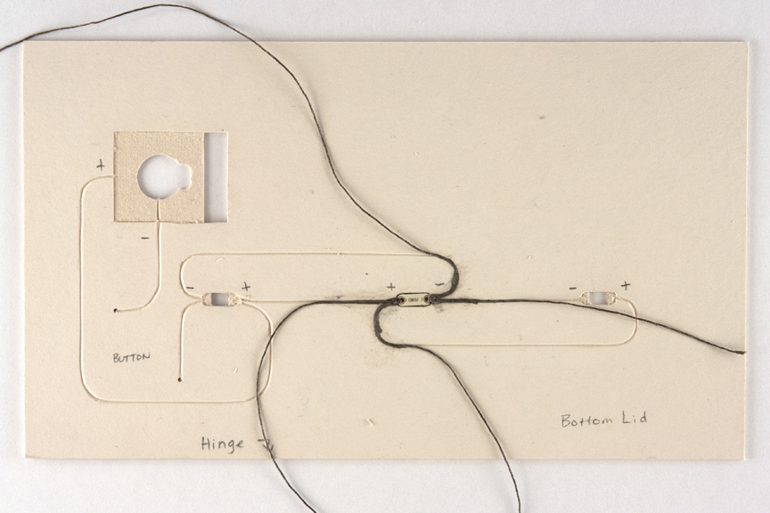
Next, cut away the opening for the bulb to fit into. Cut a small rectangle large enough for the bulb and the bump next to it. Referring to your planning drawing, mark the polarity by each light and draw the circuitry.
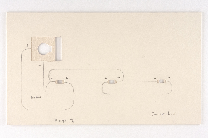 img. 16
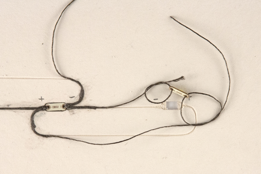
*Next to your board, set up the wiring and lights exactly like you drew it to make sure that you drew it correctly. It is easier to make changes to the wiring before you go any further.
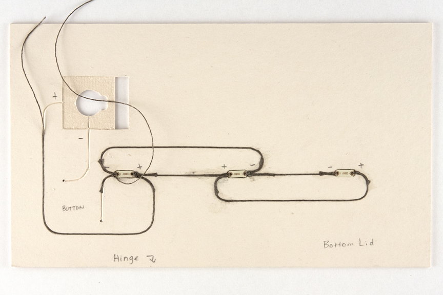
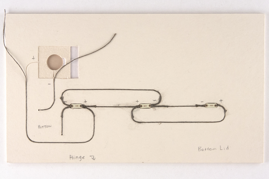
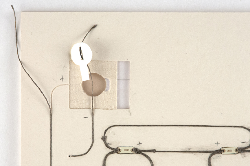
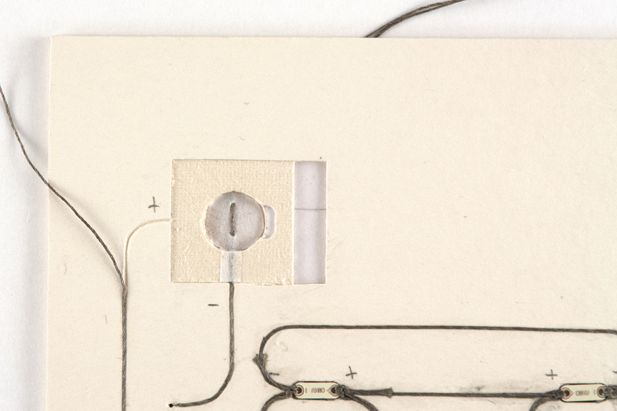
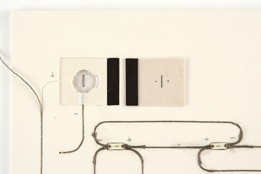
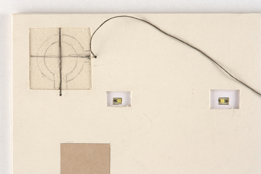
For the button, determine where you will need to poke holes to run your thread to the button connections and finish the circuitry drawing.
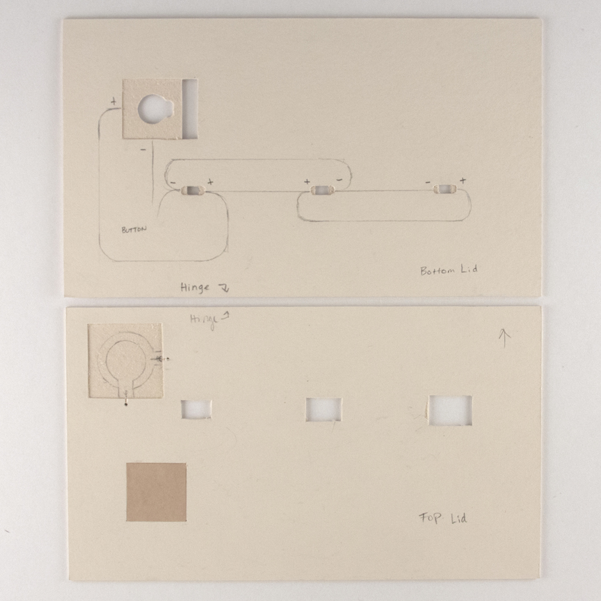 img. 17
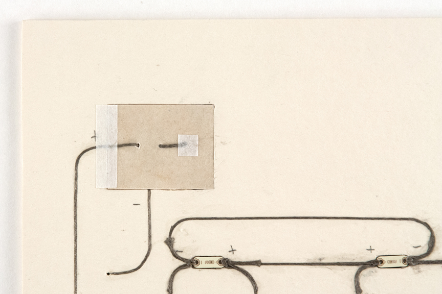
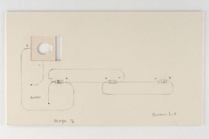 img. 18
Cut v-shaped grooves where the circuitry is drawn, and cut the channels a little wider where the threads connect to the lights.
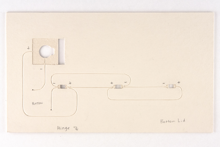 img. 19
Add the thread and the lights starting with a centrally located light.
 img. 20
Tie two threads loosely at each end of the light with an overhand knot. (a square knot is too bulky and since they will be glued into place, the threads just need to stay in place long enough for the glue to dry). When cutting the thread, leave extra-long tails for tying.
Put some glue into the channel, lay the light in place (with the positive and negative on the correct sides), and press the thread into the groove with a bonefolder (including the tail).
 img. 21
*Do no glue the thread all the way from one light to the next. Stop short at least 1 inch away so you have room to tie the next light down.
Once all four threads of the first light are secured, check the circuit to be sure everything is connected properly. Move to the next light.
With the thread from the first light, tie a loose knot to the next light. (Add an extra thread if necessary to connect to another component.) Put glue in the remaining groove and lay the light into place. While holding down the light, pull the knot tight. Trim the tail and glue in place.
Connect all lights and glue the threads just short of the battery and the button connections. Test the circuitry again.
 img. 22
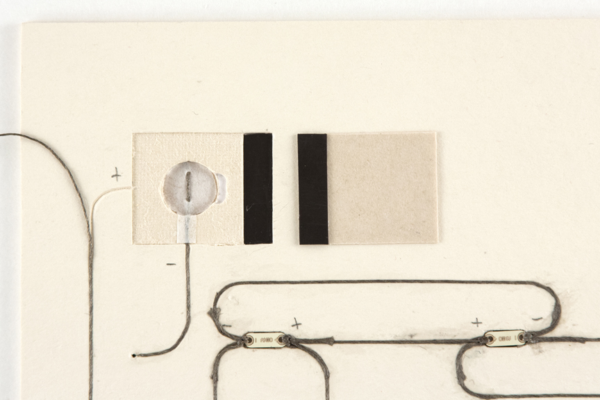
Glue the TOP LID and BOTTOM LID boards together. Be careful not to plug up the holes with glue. The boards can be put under weight but shouldn’t be put in a press, which may cause damage to the LEDs.
Feed the thread through the holes that lead to the button and glue in place on the circuitry side.
 img. 23
 img. 24
BATTERY COMPARTMENT
Cut out the paper for the battery compartment lining material. No matter how you plan to cover the compartment, you have to run the thread through it so it will touch only the bottom of the battery and cover the thread as it travels down the side. Glue this in place and trim the thread.
 img. 25
 img. 26
Glue the magnet in place in the compartment bottom and the other side to the door. Depending on your covering method, you may want to do this before the following step.
 img. 27
For the door, determine your opening method and the cover material. Weave the thread through the door so that it will come into contact with the top of the battery. Determine your hinge method, then attach the hinge material and glue everything in place.
 img. 28
 img. 29
*The door’s final lining will depend on your design and its placement in your box/book.
You can draw a line perpendicular to the thread to create a + so it acts as a guide for the battery placement. Test everything before all threads are finally glued into place.
*Sand the lid boards down if necessary
BUTTON CONSTRUCTION
The button works because it disrupts the circuit by keeping the threads from touching. Once you press on top of the button the threads come into contact completing the circuit.
 img. 30
 img. 31
Draw where your button is within the square and where your cotton batting should sit. Lay the bottom thread across the center of the compartment (vertically).
Keep your glue away from the contact points gluing above and below the area. You can cut a channel above and below the contact area for extra security.
 img. 32
Next, glue the batting into place.
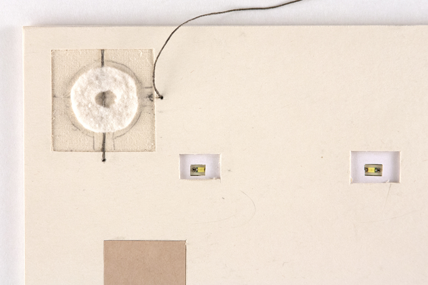 img. 33
Lay your button upside down next to the opening and glue thread in place and trim.
 img. 34
Before gluing the button into place, lay it down dry to make sure everything works. 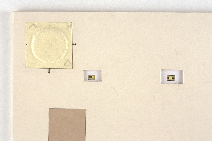 img. 35
Glue button down (just the perimeter of the button) and press in place with a bonefolder.
FINISH DESIGN ELEMENTS
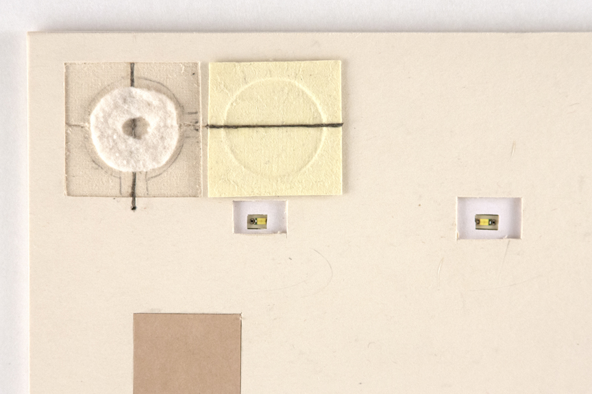
Glue in the lantern paper. (Since my design will be set into the lid, it is trimmed at this point.) Now the decorative design is finished and can be set aside.
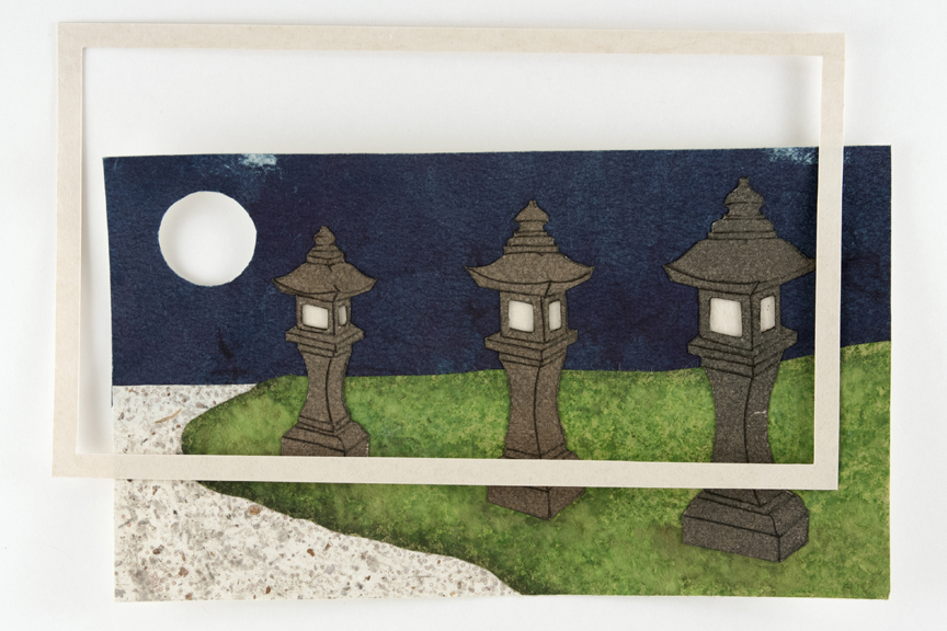 img. 36
BOX CONSTRUCTION CONTINUED
Glue laminate piece to the LID board.
 img. 37
Cut the flap board. Determine flap opening method (ribbon/cut out) and prep the board.
Go to PART 4